|
|
 |
Offers world-class industry-standard atmospheric wafer handling
robots, track systems and motion
controllers; |
|
Highly evolved designs with a cost saving alternative that can raise productivity levels and reduce operating
costs; |
|
State of the art, highly reliable robots are easily integrated into your equipment and utilize simple to use motion control software that offers exceptional reliability and unmatched
versatility; |
|
Working with semiconductor fabrication plants worldwide to increase the uptime of their existing equipment by replacing aged equipment with more reliable automation
tools; |
|
Legendary customer service, and with over 75 combined years of experience of expertise. |
|
Wafer Handling Robots
| MTBF |
60,000 Hours |
 |
| Vertical Travel |
179 mm to 432 mm |
| Reach |
Up to 366 mm plus End Effector |
| Clean room Compatibility |
Class 1 |
| Footprint |
Drop-in ATM Replacement |
| Repeatability |
+/- 0.025 mm |
| Motion Control Kernel |
32-Bit, Real Time |
| Control Architecture |
Distributed Servo |
| Drive Mechanism |
Zero-Backslash Harmonic Drives |
| Cassette Mapper |
Available as Option |
|
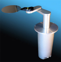
All-in-One Design:
Integraded motion controller, servo amplifier, and power supply within the robot’s cylindrical housing. No external controller or
interconnecting cabling. |
Newly developed and fully backward compatible, the ATM-100, 300 &
ATM-400 series atmospheric robots are a significant advancement in
R-Theta-Z robot design and system architecture. Benefiting from the technological advances of today's components, the robots utilize lowinertia,
quick response brushless servomotors. Coupled with zero-backlash Harmonic Drive® speed reducers, our robots offer greatly enhanced
dexterity and precision. The innovative, class 1 compatible design incorporates the motion controller, servo amplifiers, and power supply within
the robot's industry-standard cylindrical base. Our integrated design occupies less of your valuable manufacturing space.
The robot 32-bit, real-time kernel delivers accurate motion profiling along multiple path segments, and the distributed control architecture
allows seamless integration with linear tracks, pre-aligners, and other
sub-components. Networkable RS-485 and Ethernet interfaces
complement the standard RS-232 and teach pendant connections. Comprehensive emulation of traditional robot "macro" commands offer a high
level of compatibility with existing semiconductor tools. Powerful native wafer handling and scripting languages allow for simple integration of
the robot into a wide variety of new automation applications.
The robots are offered with different radial reach capabilities. Standard arm links are 5.25" long, making total available reach equal to 10.50"
plus end-effector length. If longer reaches are required, links of 7.20" are available. Z-axis vertical travel is 7" to 17". Additional options include
multiple vacuum lines, a class 1 reflective laser scanner, S2 ready, and vacuum compatibility to
10-8 torr. |
| |
ATM 407
300 MM WAFER
HANDLING ROBOT |
ATM 405
300 MM WAFER
HANDLING ROBOT |
ATM 307
200 MM WAFER
HANDLING ROBOT |
ATM 305
200 MM WAFER
HANDLING ROBOT |
ATM 107
200 MM WAFER
HANDLING ROBOT |
ATM 105
200 MM WAFER
HANDLING ROBOT |
| Integrated Controller & Power supply |
YES |
YES |
YES |
YES |
YES |
YES |
| Communications Interface |
RS232, RS485,
ETHERNET |
RS232, RS485,
ETHERNET |
RS232, RS485,
ETHERNET |
RS232, RS485,
ETHERNET |
RS232, RS485,
ETHERNET |
RS232, RS485,
ETHERNET |
| Supply Voltage |
115-240 VAC 50/60 Hz |
115-240 VAC 50/60 Hz |
115-240 VAC 50/60 Hz |
115-240 VAC 50/60 Hz |
115-240 VAC 50/60 Hz |
115-240 VAC 50/60 Hz |
| Cassette Mapping |
Optional |
Optional |
Optional |
Optional |
Optional |
Optional |
| Macro Programmable |
YES |
YES |
YES |
YES |
YES |
YES |
| Repeatability |
±0.002 |
±0.002 |
±0.002 |
±0.002 |
±0.002 |
±0.002 |
| MTBF |
60,000 hours |
60,000 hours |
60,000 hours |
60,000 hours |
60,000 hours |
60,000 hours |
| Range of Motion Theta |
360° no dead zone |
360° no dead zone |
360° no dead zone |
360° no dead zone |
360° no dead zone |
360° no dead zone |
| Speed Z Axis |
20 inches/sec |
20 inches/sec |
20 inches/sec |
20 inches/sec |
20 inches/sec |
20 inches/sec |
| Speed Theta Axis |
360° per sec |
360° per sec |
360° per sec |
360° per sec |
360° per sec |
360° per sec |
| Speed Radial Axis |
35" per sec |
35" per sec |
35" per sec |
35" per sec |
35" per sec |
35" per sec |
| Robot Hole Diameter |
11.5" |
11.5" |
9.75" |
9.75" |
8.5" |
8.5" |
| Vacuum required |
40.6 kpa - 54.2 kpa |
40.6 kpa - 54.2 kpa |
40.6 kpa - 54.2 kpa |
40.6 kpa - 54.2 kpa |
40.6 kpa - 54.2 kpa |
40.6 kpa - 54.2 kpa |
|
* The values shown are typical, please consult with the factory or refer to the website for additional information on existing and new products.
* For reference only |
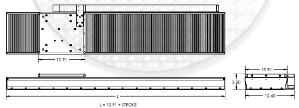
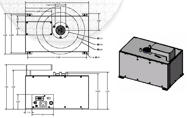
| MODEL NUMBER |
STROKE |
HEIGHT |
BODY DIAMETER |
FLANGE DIAMETER |
| ATM 10X |
7.12 [180.9] |
17.62 [447.6] |
7.95 [201.9] |
10.00 [254] |
| ATM 30X |
17.00 [431.8] |
27.50 [698.6] |
7.95 [201.9] |
10.90 [276.9] |
| ATM 40X |
13.11 [333] |
21.93 [557] |
10.83 [275] |
13.00 [330.2] |
|
| |
ARM ASSEMBLIES |
| ATM 10X |
ATM 30X |
ATM 40X |
| ATM 105 |
ATM 107 |
ATM 305 |
ATM 307 |
ATM 405 |
ATM 407 |
| A |
3.38 [85.9] |
3.38 [85.9] |
3.31 [83.9] |
3.31 [83.9] |
3.40 [83.3] |
3.40 [83.3] |
| B |
2.18 [54.4] |
2.18 [54.4] |
2.10 [53.4] |
2.10 [53.4] |
2.20 [55.8] |
2.20 [55.8] |
| C |
1.40 [35.5] |
3.79 [96.3] |
0.95 [24.1] |
3.34 [84.8] |
0.10 [2.54] |
2.29 [58.3] |
| D |
1.46 [37] |
1.57 [40] |
1.46 [37] |
1.57 [40] |
1.46 [37] |
1.57 [40] |
| E |
1.70 [43.2] |
2.05 [52] |
1.70 [43.2] |
2.05 [52] |
1.70 [43.2] |
2.05 [52] |
| F |
5.10 [129.5] |
7.22 [183.4] |
5.10 [129.5] |
7.22 [183.4] |
5.10 [129.5] |
7.22 [183.4] |
| Radius G |
1.70 [43.2] |
1.70 [43.2] |
1.70 [43.2] |
1.70 [43.2] |
2.05 [52] |
2.05 [52] |
| øH |
2.91 [74] |
2.91 [74] |
2.91 [74] |
2.91 [74] |
1.57 [40] |
1.57 [40] |
| REACH |
10.20 [259.1] |
14.44 [366.8] |
10.20 [259.1] |
14.44 [366.8] |
10.20 [259.1] |
14.44 [366.8] |
|
 |
Robot Positioning Track |
| The Robot Positioning Track is a low profile, wide footprint, linear motor powered enclosed positioning stage. Brushless linear
motors offer unparalleled performance by producing extremely smooth and backlash-free motion. The magnetically preloaded dual
parallel linear bearing rails with 4 linear recirculating ball bushing
guides provide an extremely stable platform for the wafer handling
robot. Available in travel lengths up to 160 inches, the robot positioning track is designed so that multiple independent in-line
shuttles can be installed on the same track. |
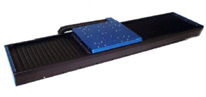 |
The Robot Positioning Track incorporates the latest in linear motion technology.
|
|
Motors: non-contact 3 phase brushless linear motor, commutated either
sinusoidally or trapezoidally with Hall Effects. The encapsulated laminated
coil assembly moves and the multi-pole single sided permanent magnet assembly is stationary.
Bearings: Linear guidance is achieved by using two parallel linear rails with four linear recirculating ball bearing guides. Clean room compatible
lubricants are used to minimize particulate generation.
Encoders: Non-contact optical linear encoders with a reference mark for homing. Multiple reference marks are available and are spaced every 50
mm down the length of the scale. Typical encoder output is A and B square wave signals but sinusoidal output is available as an option
Limit Switches: End of travel limit switches are included at both ends of the stroke. The switches can be either active high (5V to 24V) or active
low. The switches can be used to shut down the amplifier or to signal the controller that an error has occurred.
Cable Carriers: Cable guidance is achieved by using a cable carrier. The cable carriers are oversized to allow for routing of the wafer robot’s hoses
and cables. The back of the cable carrier can be easily removed and reattached to route through additional cables.
Bellows: The robot positioning track is offered with optional neoprene / nylon bellows with Mylar stiffeners. 12:1 extension to compression ratio.
Hard Stops: Hard stops are incorporated into the ends of the robot positioning track to prevent over travel damage in the event of servo system
failure.
Mounting: The positioning table is designed for base mounting of the wafer robot.
|
 |
Wafer Prealigner
| Kinematics |
Rotating Vacuum Chuck
Horizontal Linear Axis for Offset Compensation
Vertical Linear Axis for Chuck Height Positioning |
 |
| Alignment Repeatability |
Linear: +/-0.025 mm
Angular: +/-0.05 degrees |
| Maximum Offset |
Single Step Alignment: 12.5 mm
Two Step Alignment: 25 mm |
| Wafer Sizes |
125 mm, 150 mm, 200 mm |
| Wafer Configurations |
Entire SEMI Flat and Notch Specification |
| Object Opacity |
Transparent, Semi-Transparent and Opaque Wafers |
| Drive System |
Ultra Low Inertia Brushless Motors on all Three Axes |
| Load Options |
Universal Chuck and Pin Loading |
| Detection |
Optical CCD, Non-Contact |
| Alignment Time |
Less than 3 Seconds |
| Cleanliness |
Class 1 Compatible |
| Power |
115/230VAC, 50/60Hz, 65VA |
| Vacuum |
500 mm Hg |
|
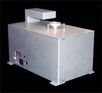
The PA-200 Prealigner is an innovative,high precision, class 1 compatible
solution including scanning electronics, motion controller and power
supply within an industry standard footprint. This unique all-in-one design
eliminates external controller and interconnecting cables while maintaining drop-in compatibility. All three axes are servo driven and equipped with
ultra low inertia brushless motors for smooth, rapid response.
The PA-200 Prealigner supports both chuck and pin load configurations
without mechanical changes. The advanced scanning head is capable of
detecting transparent, semi-transparent and opaque objects without
repositioning between different wafer sizes. The built-in intelligent
motion controller features a comprehensive set of commonly used commands to allow for the seamless integration of the prealigner into a variety of
semiconductor platforms. The PA-200 is available in bottom-entry and side-entry cable configurations. The unprecedented aligning cycle time of less
than three seconds allows for maximum throughput. |
 |
|